Free end-to-end electronics design systems. Modern problems of science and education Cross-cutting project
Creating an information system of any level of complexity goes through several main stages: setting a task, preparing a technical task, developing an information structure and a database, creating an application prototype, adjusting a technical task, creating a finished application, preparing and developing new versions. To solve the problems that arise at each of these stages, specialized tools have been created to help developers minimize time costs and reduce the number of errors. However, when moving from one stage to another, the problem of continuity and integration of specialized tools used in the development of the application arises: the requirements of analysts must be transferred to the database developers, the finished database should be transferred for the development of the user interface, upon receipt of the customer's comments on the application prototype, the technical specifications must be adjusted. In this case, it is necessary to avoid a total reworking of the entire system. In the automation systems developed earlier, these problems were solved only partially.
Approaches to application design in the proposed systems of automation of design and development of applications can be informally divided into two types, conventionally called: "to and from" and "to and from".
The first approach is promoted by developers of builders and "light" CASE tools and assumes that CASE tools are used only for design - ("before") creating a database, and application development is carried out ("from" a ready-made database) using builders that have their own tools. data model reverse engineering, class libraries and many other tools. The main disadvantage of this approach is the discontinuity of the technological process, as a result of which the data model used by the builder is much poorer than the model developed by the analyst using CASE tools or manually. The analyst is forced to convey additional information in informal ways ("voice"). In addition, in the process of developing an application, it often turned out that the standard class libraries used by the builder were not sufficient for developing a full-featured application, and each programmer had to increase the functionality in his own way, which led to a "patchwork" interface. As a result, despite the availability of convenient tools for analysts and programmers, their use does not improve the quality of the system or speed up development.
The second approach, implemented in the so-called "heavy" CASE tools, for example, in the Tau UML Suite, assumes that CASE supports the development "from" analysis "to" the construction of a logical data model and a logical application model, on the basis of which the database is created and implemented. automatic generation of program code. Tau UML Suite provides the user with an excellent toolkit for designing an application:
form content diagrams (FCD - Form Contence Diagram), which allow you to describe the structure and (to a large extent) the functionality of complex screen forms (designed to work with several tables);
Structure Charts Diagrams (SCD), which allow describing the algorithms of program modules and methods of working with screen forms (within the framework of the structural approach, working with screen forms is elegantly carried out using the so-called "predefined modules");
Form Sequence Diagrams (FSD) that define the overall structure of the application. and also link forms and algorithms (methods).
The main disadvantage of this approach is that the design ideology does not take into account the real needs of the designer, who must develop an information system with a standard interface, since the customer needs a system with easy-to-learn jobs. The designer needs a means of building a logical model of a standard interface, not a complete model of all interface elements. Detailed design of each screen form (by means of FCD or in the builder) when creating a standard interface is not only tedious, but often harmful work, and "unique" jobs, as a rule, are not numerous, they are much faster and easier to create based on a typical workplace and not from scratch. In addition, the cost of acquiring and mastering a "heavy" CASE pays off only when creating sufficiently large systems or in "line" production, many of the features provided by products of this class are not so necessary for creating a small system by developers who know the subject area well or for reproducing an existing system on another platform.
DataX/FLORIN set itself the task of developing a design technology that would provide automatic data transfer during the transition from one stage of information system development to another, would allow the creation of modern information systems with a standardized user interface in a short time and would support the full application life cycle. Such a technology was developed and called "end-to-end design technology". It allows you to link together all the stages of building an information system, from setting a task to creating paper documentation. The use of this technology makes it possible to refuse manual work on coding the base and program interfaces, makes it possible to make changes at any level of implementation, and as a result, gives the customer not only a ready-made system, but also the means for its further development and maintenance. To implement end-to-end design technology, the GRINDERY family of software products was created, with the help of which the technological gap between CASE-tools and interface programming tools was overcome. The use of software products of the GRINDERY family allows for the logical design of the application simultaneously with the development of the logical structure of the database in the Telelogic Tau UML Suite environment, then to automatically generate program code in any programming language supported by the GRINDERYTM family. Setting and changing the control parameters of code generation (attributes), as well as managing access rights and project versions, is carried out using the mechanisms of the corresponding CASE tool. Templates have been developed for the GRINDERYTM code generator to create a typical application interface. In an application with a generic interface, a workplace is created for each subject table of the database, allowing you to perform basic operations with the data (INSERT, UPDATE, DELETE, QBE) contained in this table. A workspace created for a subject table allows you to work not only with the main table, but also with other ("auxiliary" for this workspace) database tables. The specific appearance of the screen forms and the functionality of the application depend on the set attribute values. With their help, you can set, for example, the method of presenting a particular field, the headings of forms and fields, the need to present records from descendant tables and partner tables, and the mode of access to dictionary tables. The set of attributes for each table and its fields is set once and is used for all forms in which this table or its fields are available. Attributes are entered and edited either from the GRINDERY GrabberTM GUI or through the Telelogic Tau UML SuiteTM GUI. The developer can manually make changes to the application code generated by the code generator at any time.
Thus, the end-to-end programming technology developed by DataX/FLORIN and the software products created for its implementation make it possible to solve the problem of automating application design from the analysis stage to complete generation of application code with a standardized user interface.
1. A. V. Vishnekov, E. M. Ivanova, I. E. Safonova, Integrated system for supporting the adoption of design and management decisions in the system of automated integrated production of high-tech products, materials of the I All-Russian Conference "Innovations, Quality, Education", M. : MIEM, 2003
2. Vishnekov A.V., Methods for making design decisions in CAD / CAM / CAE systems of electronic equipment (in two parts), M .: MIEM, 2000 /
3. Dendobrenko B.N., Manika A.S., Automation of the design of REA, M .: Higher school, 1980.
4. Klyuchev A.O., Postnikov N.P., Technology of end-to-end design of information and control systems, Abstracts of the XXX scientific and technical conference of the faculty, St. Petersburg State Institute of Fine Mechanics and Optics, St. Petersburg: 1999. (http://www.florin.ru/win/articles/alma_ata.html)
5. Norenkov I.P., Kuzmik P., Information support for high technology products. CALS - Technologies, ISBN 5-7038-1962-8, 2002
6. Malignac L. Further expansion of the functionality of CAD // Electronics, 1991, volume 64, no. 5.
7. Gan L. Design automation tools that provide parallel work on projects // Electronics, 1990, volume 38, no. 7, p. 58-61.
8. A. Mazurin, Trends in the development of Unigraphics in 2001, CAD and Graphics magazine, No. 12, 2000 (http://www.sapr.ru/Article.asp?id=671)
9.http://www.spb.sterling.ru/unigraphics/ug/cad/index.htm
10. Smirnov A. V., Yusupov R. M. Parallel design technology: basic principles and implementation problems, Design automation, No. 2, 1997 (http://www.osp.ru/ap/1997/02/50.htm )
11. Nevins J.L., Whithey D.E. Concurrent Design of Products and Processes. - McGraw-Hill, New York, 1989
12. R.P. Kirshenbaum, A.R. Nagaev, P.A. Palyanov, V.P. Freishteter, D.V. , 1998
13. Ishi K., Goel A., Adler R.E., A Model of Simultaneous Engineering Design - Artificial Intelligence in Design / Ed. by J.S. Gero, N-Y: Springer, 1989, p483-501.
14. Structural analysis in MSC/NASTRAN for Windows http://www.dmk.ru/compold.php?n=NA==
15.http://www.nastran.com
16.http://www.ansys.com
17.http://www.cad.ru/cgi-bin/forum.pl?theme=762&reply_id=4328&start_id=
18.http://www.ibm.com/en/catia
19.http://www.solidworks.ru
20. CAD Solutions - solution of engineering problems in the field of mechanical engineering http://cadsolutions.narod.ru/Pages/CadCamCae/UGNX.htm
21. S. Maryin, What is Unigraphics., CAD and graphics magazine, No. 7, 2000.
22. E. Kartasheva, SDRC Integrated Technologies, Open Systems Journal No. 5, 1997, pp. 72-77.
23 Math. Models made in CAD/CAM system Pro/Engineer, http://ws22.mech.unn.runnet.ru/CADCAM/ProEngineer/GAZ/J1.html
24. Computer-Aided Design Systems: An Illustrated Dictionary, ed. I.P. Norenkova., M.: Higher school, 1986.
25.http://arkty.itsoft.ru/edu/control/cada0b.htm
26. http://www.iatp.am/vahanyan/systech/v.htm
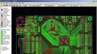
Gone are the days when, to develop the layout of a printed circuit board, the designer armed himself with a sheet of paper, a sharpened pencil, an eraser, and turned on his spatial imagination. This was a difficult, tedious and unproductive business. It is no coincidence that almost from the moment of its creation, attempts were made to adapt computers to solve design problems. As a result, many Computer-aided Design (CAD) or CAD (Computer-Aided Design) systems have been created, focused on solving various design and construction problems. CAD used to automate the design of electronics is often abbreviated as EDA (EDA - Electronics Design Automation). Typically, an EDA end-to-end design system includes an electrical schematic editor and a PCB editor. Recently, such systems increasingly include electrical circuit simulation tools that allow you to explore the operation of an electronic device even before it is embodied in hardware.
As for electronics, back in the 80s of the last century, then still Soviet designers, an excellent commercial CAD PCAD became available. This CAD was so successful that for many years it became a kind of industry standard. Despite the emergence of new generations of CAD and operating systems, "dos" PCAD versions 4 ... 8.7 are still actively used in many design bureaus. This is explained not only by the positive qualities of the "dos" PCAD, but also by the fact that for many years of use, a large amount of documentation, libraries has been developed for it, and the design and production process has been optimized. For designers who are not burdened with such baggage, a huge number of CAD systems are offered on the market, the list of which is constantly updated. Modern CAD systems automate the work of a designer to an even greater extent, allow the joint work of many designers, which guarantees better results in a shorter period of time.
Thanks to the increasing penetration of computers into non-professional areas, as well as their use for education, the latter have become available to a large number of non-professional designers and students. Non-professional designers, in this context, are those who only occasionally engage in construction in connection with their professional activities or hobbies.
Usually non-professionals try to use the same CAD systems as professionals. But, not having much financial income from their activities, they cannot honestly afford to buy expensive professional CAD (usually, the cost of professional and therefore commercial CAD rarely drops below $ 2000 USA) and use various hacked versions of CAD that are on the Internet. It is clear that in this case you have to put up with the unstable operation of such software, the lack of technical support, as well as the possibility of infecting your computer with viruses. In addition to all of the above, such use is simply illegal!
Without focusing on the moral aspect of the free use of commercial software, let's draw the attention of non-professionals to the fact that on the same Internet you can find many absolutely free CAD systems that are quite capable of solving all the problems of a non-professional developer. Importantly, free CAD software usually allows faster learning and a lower level of user expertise. For example, the volume of documentation for basic commercial CAD reaches thousands of pages, while a complete description of many free CAD systems can easily fit in several magazine publications. If you don't build all the time, it's better to flip through a few pages on occasion than to go through a thick manual every time!
Much of the above also applies to professional developers of small, growing firms, who incur large costs at the stage of formation and therefore also do not have the opportunity to purchase commercial software.
Let's make a short review of free programs designed for designing printed circuit boards. There are basically two types of such programs on the Internet. On the one hand, such programs are created by various companies associated with the production of printed circuit boards or the sale of components, and on the other hand, amateurs or groups of amateurs are involved in the development of such programs.
The category of the first includes quite well-known programs in the amateur environment. Express PCB[http://www.expresspcb.com/ ], Pad2Pad[http://www.pad2pad.com/ ] and PCB Artist[http://www.4pcb.com/free-pcb-layout-software/index.html]. Like many programs of this class, Express PCB, Pad2Pad and PCB Artist were created to promote the services of their companies and therefore have reasonable limitations, which is that at the output we get a project in some closed format, which we can send only to a specific printed circuit board manufacturer . And this is not good. True, domestic amateurs rarely privately order printed circuit boards on the side. Usually they are drawn in the old fashioned way by hand or using laser-ironing technology. And since Express PCB, Pad2Pad and PCB Artist are able to print results, sometimes this is already enough for handicraft board manufacturing.
A little aside from the above programs is the relatively recent EDA DesignSpark PCB. Software package DesignSpark PCB[http://www.designspark.com/ ] was launched in July 2010 and was developed by RS Components, headquartered in Corby, UK. This software package is absolutely free. To activate the program, you only need a simple and free registration on the company's website. At the same time, DesignSpark PCB does not contain any restrictions either on the number of circuit elements or on the time of use. Unlike the above programs, DesignSpark PCB does not try to bind users to a specific manufacturer and generates output files in popular production formats Gerber, DXF, Excellon, IDF, LPKF. This program has been done to a very good professional level and includes all the necessary components such as a schematic editor and a PCB editor. In the schematic editor, the user can easily draw schematics and connections. At the same time, the scheme may contain many sheets interconnected in a complete project. The latter has the functions of autolayout and autorouting. At the moment, there is a large online community of users of this program, where everyone can find support on issues of interest to him. DesignSpark PCB supports popular simulators such as LTSpice, LSSpice, TopSpice and TINA. Users have the ability to import their designs from these PCB design software. The program interface includes a specialized calculator that allows you to calculate the width and resistance of tracks, the optimal current density and temperature rise of the track, as well as the resistance of vias.
KiCad consists of a schematic editor Eeschema, PCB editor pcbnew and Gerber viewer Gerbview. A pleasant surprise is that the Russian language is provided in the program options, and there is also help in Russian. The schematic editor provides the creation of single-sheet and hierarchical circuits, electrical rules control (ERC), the creation of a list of circuits (netlist) for pcbnew or Spice. The PCB editor provides the development of boards containing from 1 to 16 layers of copper and up to 12 technical layers (silkscreen, solder mask, etc.), the generation of technological files for the manufacture of printed circuit boards (Gerber files for photoplotters, drill files and placement files components), printing layers in PostScript format. Gerber Viewer allows you to view Gerber files.
 |
End-to-end design The point of end-to-end technology is to efficiently transfer the data and results of a particular current design stage to all subsequent stages at once. These technologies are based on the modular construction of CAD but the use of common databases and knowledge bases at all stages of the project and are characterized by a wide range of modeling and control at all stages of design. Parallel design The technology of parallel design is a development of end-to-end design technology.
Share work on social networks
If this work does not suit you, there is a list of similar works at the bottom of the page. You can also use the search button
Lecture #3
Basic design technologies CAD/CAST/SAIT
The most promising technologies today are:
- end-to-end design
- Parallel Design
- Top-Down Design
CALL technology
The main idea is to create an electronic description and support of the product at all stages of its life cycle. An electronic description must comply with accepted domestic and international standards in this subject area. This is a technology of information support for the creation of a product.
end-to-end design
The point of end-to-end technology is to efficiently transfer the data and results of a particular current design stage to all subsequent stages at once.
These technologies are based on the modular construction of CAD, but the use of common databases and knowledge bases at all stages of the project and are characterized by a wide range of modeling and control at all stages of design.
End-to-end CAD, as a rule, are integrated, i.e. have alternative algorithms for the implementation of individual design procedures.
Parallel Design
Parallel design technology is a development of end-to-end design technology.
In parallel design, information regarding any intermediate or final characteristics of the manufactured product is formed and provided to all participants in the work, starting from the earliest design stages. In this case, the information is predictive in nature. Its obtaining is based on mathematical models and methods of predictive evaluation of various options for project strategies, i.e. selection of the fundamental characteristics of the product under development, determination of development quality criteria and selection of algorithmic and development tools. The assessment can be made on the basis of analytical models, on the basis of statistical methods and on the basis of methods of expert systems.
The technology of parallel design is implemented on the basis of integrated tools for predictive evaluation and analysis of alternative design solutions, followed by the selection of a basic design solution.
A predictive assessment can be carried out both in relation to the entire project (then we are talking about the stage of advance design), and in relation to individual design stages.
The fundamental difference between parallel design and end-to-end design is that information does not just go to all subsequent design stages, but, since all stages begin to be performed simultaneously, information goes to both all previous and all subsequent design stages.
Winning parallel design as the whole project, since at a particular design stage, criteria from other stages are taken into account.
Information appears to all participants in the development from the terms of reference and based on the stages of advance design.
For the first time, the parallel engineering environment was proposed by the company Mentor Graphics based on the principle of combining all design tools and data in one continuous and flexible product development process.
This infrastructure includes:
- Design Management Environment
- Project data management system
- Decision support system
Top-Down Design
Top-down design technology involves the engineer starting to work on a project at a high level of abstraction, followed by detail.
The main task of a manager or engineer is to determine the optimal conceptual solution (as a rule, a more rational one is sought) for the choice of design algorithms, as well as effective design tools. In other words, determining the correct design strategy based on fairly general and vague information.
This problem is solved on the basis of prescriptive tools, i.e. programs that provide communication between the stages of the functional-logical, technical (design) stage of design and the stage of technological preparation of production.
At the same time, dictative tools are used both at the level of individual project procedures, and at the level of the project as a whole.
Top-down design allows you to get a product with higher performance characteristics and create a reliable device.
All modern CAD manufacturers are based on top-down design technology.
The structure of the design process of the electronic computer technology module
- Conceptual (avan) design
- Functional-logical design
- Functional diagram design
- Design of test programs and tests
- Design (technical) design
- Structural advance design
- Formation of a set of rational options
- Analysis of alternative software modules for the implementation of subsequent design procedures and selection of the most appropriate ones (adapting CAD to the design object)
- Selection of the basic version of the design design (selection of the metric and topological parameters of the object)
- Layout of structural modules
- The stage of placing elements on the surface of the module
- Routing Signaling Connections
- Technological preparation of production (creation of route maps of the production process)
- Preparation of technical documentation
Other related works that may interest you.vshm> |
|||
| 2735. | Intelligent technologies for designing information systems. Methodology for designing software products in the presence of a prototype | 115.24KB | |
| On the example of the conceptual design of an automated information system that performs the examination of audio products, we will present a general methodology for creating an information system project. The purpose of creating an automated system is to develop a tool for conducting a high-quality objective examination of audio products in accordance with Federal Law No. 436 On the protection of children from information that is harmful to their health and development. The object of research will be audio products. By destructive information we mean... | |||
| 6616. | Technological unification. Varieties of technological design. Functional diagram of CAD TP | 19.37KB | |
| Technological unification bringing to a single system of processing methods. These are tasks such as the choice of processing methods for the type of equipment, the type of tool, the assignment of the basing scheme of the installation method of the part, the formation of the scope of operations, the determination of the sequence of operations, the selection of the type of workpiece, the determination of the sequence of transitions in operations. How does the technologist make a decision in each of the listed cases Let us consider as an example the problem of choosing a processing method. The technology is known for proven... | |||
| 7344. | Basic Information Technology | 25.92KB | |
| Multimedia technologies can be defined as a system of computer information technologies that can be used to implement the idea of combining heterogeneous information in a single computer information environment. There are three main principles of multimedia... | |||
| 7633. | Formalization of EIS design technology | 15.23KB | |
| Formalization of EIS design technology The complexity of the high costs and laboriousness of the EIS design process throughout the entire life cycle necessitates, on the one hand, the choice of an adequate design technology for an economic object, and, on the other hand, the availability of an effective tool for managing the process of its application. From this point of view, there is a need to build such a formalized model of design technology when, on its basis, it would be possible to assess the need and possibility of using... | |||
| 1990. | BASIC CATEGORIES OF ANALYSIS | 42.12KB | |
| The concept of routine was introduced by Nelson and Winter in relation to the activities of organizations and defined by them as "normal and predictable patterns of behavior." However, routine behavior is characteristic not only for organizations, but also for individuals. In relation to the latter, routines can be divided into two categories | |||
| 16940. | 19.79KB | ||
| Analysis of the concept of law as an institution can be reduced to the concept of a social contract. With a broader interpretation of the concept of a contract, one can actually put an equal sign between the concept of a social contract and a reflexive norm. There can be no right without a contract at all, since the realization of any rights is always someone's duty. In modern legal literature, the concept of a contract is usually omitted. | |||
| 9290. | Terminology and basic indicators of financial management | 26.85KB | |
| The value added indicates the scale of the enterprise and its contribution to the creation of national wealth. We subtract from the DS the cost of wages and all the associated mandatory payments of the enterprise for social insurance, pensions, and so on. as well as all taxes and tax payments of the enterprise, except for income tax, we will receive BREI ... | |||
| 8040. | CAD organization | 7.99KB | |
| A CAD subsystem is a part of CAD allocated according to some criteria that allows you to get complete design systems. CAD is divided into design and service subsystems. At the output of this system, we get a functional diagram, then a logical diagram, and at the output, a circuit diagram. | |||
| 7215. | Design and CAD | 19.8KB | |
| One of the most famous foreign design automation systems is UTOCD CAD by utodesk, and one of the most famous domestic design automation systems used in mechanical engineering is Ascon's KOMPAS CAD, which includes all the necessary components of CD CAM systems. Unlike KOMPAS, utoCd is a more flexible system, but at the same time, the most complex one, since the capabilities of utoCd allow it to be used in various design areas. CAD utoCd 2004 First utoCD was... | |||
| 6614. | Description of CAD | 17.54KB | |
| The Compass system of the Russian company ASCON. The Compass 5 version includes the Compass-Graph drawing and graphic subsystem, the Compass-3D geometric modeling subsystem | |||
Methodology for organizing "end-to-end design" in AutoCAD using LOTSMAN PGS
1. Theory
1.1. What is end-to-end design
End-to-end design in this context is: one of the options for organizing group work with the ability to instantly update repetitive graphic data on all project drawings. In this case, any graphic materials (in our case, DWG files) can be logically assigned the status of "data source" or "data importer". The data importer will include the data source. And easier - a link to the data source will be inserted into it.
For example: a general planner engineer develops drawings of a GP set, on the basis of which network engineers develop plans for laying external networks. "networkers" need to know the position of the designed building, driveways, sidewalks and the existing topographic situation. They are forced to wait for the "general planner" until he finishes the formation of his drawing. In turn, the "general planner" needs topography from the "topographers" and the contours of the designed buildings from the "architects" to create the general plan.
Task: reduce waiting time, increase the efficiency of interaction between specialists.
The end-to-end design technique allows you to organize communication between all design participants at the level of the graphic environment through the AutoCAD "external links" tool.
AutoCAD tool "external links" - allows you to organize a link between two or more drawings. Those. I can import (hereinafter, this concept will mean the _attach command, which is also the insertion of an external link) into my drawing a fragment (after inserting, we can trim the external link - assign a display border) from any other drawing that another engineer created, even if he is editing it at the moment. In this case, the fragment inserted into my drawing will be updated on its own when the data source changes. Moreover, if new layers appear on this fragment that I may not need, I will be informed about this and in a timely manner I will be able to turn off their display or override their properties (new layers matching filter, in the layer manager). Those. I will always have up-to-date information received from other design participants and can start work earlier, before they finish their drawing completely, as soon as I see that there is enough data to start designing.
For example: as in the old fashioned way - network engineers of 5-7 people are forced to wait for the "general planner" until he finishes the drawing of the general plan. At some stages, they "networkers" can take intermediate versions of the general plan from him and copy them into a drawing, start work (while the copies are completely independent of the source). With any change in the general plan, they are forced to constantly update the data from the general planner and replace them in their drawings with new ones. At the same time, regularly spending time on separating the "grains from the chaff", suffering on the transfer from one scale to another, etc. But the outcome with this technique is often the same. The data is taken once and is no longer updated. And at a certain stage, a number of designers have several versions of the same data that begin to develop in parallel, eventually leading to inconsistencies in the parts of the project, which usually result in wasted time and correction of drawings at the last moment.
So, the use of the “end-to-end design” technique allows:
eliminate the appearance of inconsistencies between individual sections of the project
because it allows you to track the update of the source data in real time (excluding work in an unnecessary direction)
this eliminates manual updating of the source data (data is imported once and updated automatically when the source changes)
With this scheme, it is possible to minimize the human error factor that occurs due to insufficient awareness of the project participants about the progress of the process.
1.2. The end-to-end design process imposes certain requirements on the skills and style of working in the AutoCAD program, as well as on the version of the software product itself.
Skills:
Designers must be able to:
work with the layer properties manager.
work with the layer states manager.
use a set of commands for "external link" objects.
Style:
the designer must group all the objects into layers, creating a "logistics" that meets the needs of the subcontractors, providing the ability to override the properties of the layers.
the design team must have a common syntax for naming layers. (i.e. it’s more logical to name the main axes of the building as “Main Axes” and not “Main Axes”. Because, in the list of layers sorted alphabetically, “Main Axes” will be next to any layer starting with the letter “G*”, but not next to the layers "Axes intermediate" and "Axes additional").
Version:
the format version of the source drawing cannot be later than the version of the drawing into which the data is being imported.
2. Practical example (video)
Below is a video describing the entire process of organizing end-to-end design. Naturally, it is understood that a separate specialist works on each drawing (set). That is, the whole process, with the right approach, can be safely called automated group design.
3. Practical example (in screenshots)
On a conditional - practical example, I want to show how the concept described above is organized. For convenience, LOTSMAN PGS will act as a storage medium for design data, but it can also be a regular folder on a network drive.
Design members:
Construction Architect,
general planner,
HVAC engineer,
TGV Engineer,
Electrical Engineer.
3.1. Initial data
The GUI publishes the source data in a folder of the same name. As the initial data, in the example, there will be a topographic survey.
Screenshot. 1. Project tree (in the program LOTSMAN PGS)
3.2. AC section
The AU designer is the first to be included in the design process. Based on the assignment issued by the GUI, or previous design developments. In this example, it does not matter in what form the task is received by this design participant. The designer develops a set of speakers, which includes floor plans, facades, sections, nodes, etc. It works in the "1 AC" folder located in the root directory of the project.
The rest of the design participants developing in the direction of the master plan and external networks from the entire set of AS need only the ground floor plan and the underground part plan (if there are differences in their configuration - which are not in our example). Those. the drawing will act as a data source for a number of child drawings.

Screenshot. 2. In the drawing settings, it is important to set the correct parameter of the drawing unit; on the construction drawings of this set, this is usually millimeters (Menu: “Format>

Screenshot. 3. AutoCAD space. On the right is an example plan of the first floor of the AS set. On the left, the layers used in the drawing.
3.3. GP section
In parallel, the general planner may be included in the design process. It runs in the "2 GPU" folder located in the root directory of the project. His drawing will be the data importer: topography (source data) and ground floor plan (AC set).

Screenshot. 4. In the drawing settings, it is important to set the correct drawing unit parameter, in master plan drawings it is usually meters (Menu: "Format > units" or the _UNITS command)
Both drawings (topography and ground floor plan) are connected through the external reference insertion tool (Menu: "Insert > Link to DWG" or the _attach command), but first we need to find out the paths to the files, in the LOTSMAN PGS program this is done as follows:

Screenshot. 5. The window of the file panel of the LOTSMAN PGS project is an analogue of Windows Explorer.
A feature of the design organization using LOTSMAN PGS is that the central file storage is a database on a remote server, synchronized with a local folder, in which a copy of the project directories is created. The only difference from the system in which all design participants work on a shared network drive is that the PGS LOTSMAN acts as a means of synchronization between users and the server.

Screenshot. 6.1. Topography xref insertion window. The insertion point remains 0,0,0. Because According to the rules (de facto), the coordinates on the crosses of the topography must match the coordinates in AutoCAD.
Please note that since the correct drawing units (_UNITS) were set in both drawings, the block insertion units are determined automatically, that is, the ground floor plan will be automatically reduced by 1000 times when inserted.

Screenshot. 7. The topography and ground floor plan are combined on the master plan sheet.

Screenshot. 8. Change the color and thickness of the topography layer display. Thus, we override the properties of objects that have the "ByLayer" attribute set for the color and thickness of the lines. (in our example, in the topography file, this is exactly the case)

Screenshot. 9. Freeze unnecessary layers (two different ways are shown, through the ribbon menu - on the left and through the main menu - on the right)
Freeze the layers (simply by clicking on the object in the drawing):
Intermediate axles
Additional sizes
Intermediate sizes
load-bearing walls
Self-supporting walls
Leaving layers:
Main axles
Main dimensions
External walls

Screenshot. 10. Creating a layer state (two different ways, through the ribbon menu - on the left and through the main menu - on the right)
3.4. NVK section (similar to other external networks)
Behind the general planner, a specialist in external water supply and sewerage networks may be included in the design process. It works in the "3 NVK" folder located in the root directory of the project. His drawing will be the data importer: from the master plan.
Repeat procedure Screenshot. 4, copy the path to the master plan file, similarly to Screenshot. 5. Insert the master plan file in the same way as Screenshot. 6. The insertion point remains 0,0,0. Because according to the rules, the coordinates on the master plan crosses must match the coordinates in AutoCAD.

Screenshot. 11. A similar picture is observed.

Screenshot. 12. Apply layer states (the screenshot shows how this is done, through the ribbon menu. Through the main menu: “Format> Layer States Manager” is obtained similarly.)

Screenshot. 13. After applying the layer configurations, the following picture is observed.
Further, in a separate layer, this communication network is drawn (in the example, this is Water supply to external networks). In the example, I didn't use any special linetypes, but you can use special linetypes: - in - , -- kn -- and others. You can create them yourself, or use ready-made ones.

Screenshot. 14. This is what the result looks like. But according to the rules for the implementation of drawings of external communications, we must display other designed communications with a thin line.
Therefore, we connect the file "Master network plan.dwg" to the drawing, which in our example will be in the "2 GP" folder of the project

Screenshot. 15. Insert the "Master Network Plan.dwg" in the same way as it was done on the Screenshot. 6. The insertion point remains 0,0,0. Because if all project participants observe a rigid coordinate reference, when inserting relative to the zero point, the inserted objects will take the correct position.
While the file "Master plan of networks.dwg" is empty, but soon it will be filled with links to other project files and will keep us informed of changes in adjacent networks, performing a coordinating role.
3.5. Master plan of networks
After creating files with networks. The engineer tasked with assembling the master network plan includes each of the network plan drawings in the Master Network Plan file. Those. in this case repeats the procedure described in the Screenshot. 6, for files:
Water supply outdoor networks.dwg
Sewerage external networks.dwg
Gas pipeline external networks.dwg
outdoor lighting.dwg
After inserting external links to the above files into the master plan file, adjacent networks appear in each file with networks. In this case, a message may appear:

But this is not an error, but only evidence that the file with our particular network is already present (as an external link) in the network master plan file and this is good.

Screenshot. 16. This is how the plans for the networks of sets will look like: NVK, GOS, EN.
Now it remains to change the line thickness of adjacent networks in the layer properties (we make them thin), and make the thickness of the designed network higher (thicker). On the screenshots 17, 18, 19, 20. Examples are presented - how the plans of the NVK, GOS, EN sets will look after setting up the layers.

Screenshots 17, 18, 19, 20
3.6. Layer matching
Layer alignment is an AutoCAD tool that will keep up to date with all changes in drawing layers inserted as xrefs. Example: If the master planner creates new layers in the master plan drawing, for example: blind area, paths, etc. Engineers designing external networks will be instantly informed about the changes after the general planner saves his drawing (and saves the changes to the server, in the case of working with LOTSMAN PGS). They will see them in the Layer Properties Manager, in the "Inconsistent New Layers" filter. To match a layer (that is, to remove inconsistent new layers from the filter), just right-click the layer and select "layer match".
In order for AutoCAD to track changes in the layers of xref files, you need to configure the layer settings in a certain way. As in screenshot 21.

Screenshot. 21. Setting the parameters of the layers. We put checkmarks on the items: evaluate new layers added to the drawing. Notify about the presence of new layers (in this paragraph we set events in which the program will notify us about the appearance of inconsistent layers) [For example, the "Insert / Reload external links" event will notify about the appearance of new layers when updating an external link. An example is below in screenshot 22.]
Screenshot. 22. Notification of a new layer loaded from a drawing of a reference file
And many may wonder how the LOTSMAN PGS program is useful in organizing end-to-end design.
Each time the original xref drawing is saved, a message pops up (see Screenshot 22), and xrefs in the drawing accumulate up to 5 or more units. And the constant appearance of this message purely psychologically over time leads to the fact that it begins to distract from work and annoy.
When using LOTSMAN PGS, before updating the local copies of the source files, we will see an icon in the file panel. That the source file is updated (on the server) and the local copy needs to be updated (with which AutoCAD works), that is, we ourselves can initialize the update procedure to reduce small portions of updated information by downloading updates, let's say no more than once an hour. That will add dimension to the design process.
The database stores all versions of files. This simplifies rollback and increases the reliability of information storage. In addition, we can track the entire history of file operations. For example, find out who last opened, edited and saved a file.
3.7. Underwater rocks
A certain qualification of working with the AutoCAD graphics program is required.
It is convenient to transfer parts of the project to third-party organizations through the publishing tool (the FORMSET command)
3.8. Technical sides
With this method of organizing work:
The size of the drawing files is reduced by replacing the physical duplication of graphic information with a logical one.
It is convenient to transfer parts of the project to third-party organizations through the publication tool (the FORMSET command).
1To reveal the essence of the professional activity of a civil engineer, the article considers the concepts of "design" and "design" activity. To prepare future specialists of the construction profile for design activities, the paper considers the method of end-to-end design of objects of professional activity. This method is based on the principle of fundamentality and professional orientation, carried out through the integration of natural sciences and special disciplines. It is also shown that the theoretical model of the method of end-to-end design of objects of professional activity is a system of actions that allow the teacher to more successfully organize the process of teaching physics. The main stages of the method of end-to-end design of objects of professional activity are singled out, using the example of studying the course of general physics.
design
design activity
end-to-end design
vocational training.
1. State educational standard of higher professional education. Direction of a graduate 653500 "Construction" [Text]: GOST VPO 653500 - 2000. - Introduction-2000 - 02 - 03 - M. - 2000. - 60 p.
2. Jones, J.K. Design methods [Text] / J.K. Jones. - 2nd ed., add. - M.: Mir, 1986. - 326 p., ill. - Zagl. 1st ed: Engineering and artistic design.
3. Sazonov, V. B. On the question of constructing the concept of design [Text] / V. B. Sazonov // Proceedings of VNIITE. technical aesthetics. Issue. 8. (chap. 13).
4. Dictionary of the Russian language [Text]. - M.: Russian language, 1987. - T. 3. - 752 p.
5. Federal state educational standard of higher professional education in the direction of training 270800 Construction (qualification (degree) "bachelor") [Text]: FGOST 270800 - 2010. - Approved.2010 - 18 - 01. - M. - 2010. - 32 p. .
6. Philosophical dictionary. Encyclopedia of Philosophical Terms Online http://www.onlinedics.ru/slovar/fil/t/proektirovanie.html Design (date of access: 03/16/2012).
7. Large explanatory sociological dictionary of terms online http://www.onlinedics.ru/slovar/soc/t/proektirovanie.html (date of access: 03/16/2012).
8. Kurbatov V. I., Kurbatov O. V. Social design: Textbook [Electronic resource]. - Rostov n / a: Phoenix, 2001. - 416 p. - P.6-68. - Access mode: http://socpedagogika.narod.ru/Proektirovanie.html (date of access: 03/16/2012).
In connection with the transition to two-level training in the system of higher professional education, on the one hand, and the increase in professional requirements for a future specialist, due to the social order, on the other hand, leads to the search for new, more effective methods of training civil engineers. An analysis of the requirements formulated in the FSES HPE of the second generation in the form of qualifications and the third generation in the form of a list of competencies allows us to state the fact that one of the main types of professional activity of specialists in the field of construction (engineers, bachelors, masters) is design activity. So, for example, in the FSES VPO of the second generation for the direction 653500 - "Construction" it was said that the future civil engineer should "participate in the implementation of the developed solutions and projects, in the construction, installation, adjustment, testing and commissioning of the designed products, objects, engineering systems and structures, to conduct engineering surveys and surveys necessary for design work on the production of materials and products, on the construction, reconstruction and repair of facilities and engineering systems and structures for the training of civil engineers ... ".
According to the new educational standards of the third generation, containing two-stage training, a graduate in the field of study "Construction" (bachelor) must have significant professional competencies, such as: possession of methods for conducting engineering surveys, technology for designing parts and structures in accordance with the terms of reference using standard applied, calculated and graphic software layouts; conducting a preliminary feasibility study of design calculations, development of design and working technical documentation, registration of completed design work, monitoring the compliance of developed projects and technical documentation with the task, standards, specifications and other regulatory documents; the ability to apply the basic laws of natural sciences, as well as methods of mathematical analysis and modeling, theoretical and experimental research in design and professional activities.
Thus, the changed qualification requirements for the training of a civil engineer, according to the third generation of the Federal State Educational Standard of Higher Professional Education, and the insufficient development of methods for coordinating natural sciences, general professional disciplines and disciplines of specialization in teaching students design activities determine the relevance of our study. The aim of the study is to develop a method for the formation of the foundations of design activities in physics classes, based on the integration of general education and special disciplines.
To search for new approaches to teaching future civil engineers professional (design) activities in physics classes, we will clarify the concept of "design", "design" and "design" activities.
Design as a type of human activity is not new, since the main types of engineering activity began to form already in the 18th century: invention, design and design elements. Initially, the concept of "design" was associated directly with the activities of draftsmen and the need for graphic reproduction of creative ideas. As production developed, the concept of "design" became more and more complicated. Now, in addition to performing drawing work, design included the organization of design activities, calculations, and the selection of the most optimal materials for future structures or engineering systems. As an independent field of activity, design becomes later, when there is a division of responsibilities between architects and builders - architects are responsible for developing the external appearance of the structure, calculating the main technical parameters and making drawings, and builders are only engaged in materializing these engineering ideas.
At present, design ideas have spread to various types of activities: design design (synthesis of technical and artistic design), pedagogical design, social design, etc. Design has become style form modern thinking, one of the most important typological features of modern culture in almost all of its main aspects related to human creative activity.
The central concept and end result of design is a project, the subject content of which is: 1) a developed plan for creating something, including a description, drawings, layouts, etc.; 2) the preliminary text of any document submitted for discussion, approval; 3) idea, plan of action.
To identify the essence of engineering design activities, one should also detail the interpretation of the concept of "design":
- the process of creating a prototype, a prototype of an alleged or possible object, state, specific activity, the result of which is a scientific, theoretical and practically justified definition of options for the predicted and planned development of new processes and phenomena;
- forecasting the implementation of something, an assumption, a prerequisite for doing something, arranging; building process;
- project creation activities. Design is characterized by two points: the ideal nature of the action and its focus on creating something in the future;
- one of the forms of anticipatory reflection of reality, the process of creating a prototype (prototype) of an alleged object, phenomenon or process using specific methods.
Design is a specific form of manifestation of the prognostic function of management, when a possible image of a future material or ideal reality is created. The purpose of design is such a transformation of reality when objects, phenomena or processes are created that would meet the desired properties;
5) a process that initiates changes in the built environment.
It can be seen that the meaning of the concept of "design" can fluctuate over a wide range, but an integral part of the project activity of the future engineer is creative activity aimed at creating the final result in the form of an idealized object (system) embodied in reality. Creating a project requires the student not only to know the basics of design, but also the ability to select the most optimal options for solving a particular problem that arises in the process of design work. In this regard, creative activity is closely intertwined with scientific and research activities. It is the skillful combination of these activities that helps the student to prepare a project at a high professional level. Summarizing all the considered interpretations of the concept of "design", we can conclude that design is one of the types of engineering activity, which is understood as a purposeful step-by-step system of creative actions to create the proposed object (thesis and course design, engineering structure, system or structure), by highlighting and transforming the interconnected elements of the predicted object.
Preparing a student for engineering design activities is associated with the study of general professional and special disciplines aimed at the formation of professional knowledge, skills and abilities. However, despite the importance of major disciplines in the implementation of the graduation project, for the most successful mastery of design methods, it is necessary to introduce elements of design activity into the educational process already in the junior years when studying general education disciplines.
The concept of "design" is closely related to such concepts as "design" and "project" activities. In the scientific and pedagogical literature, the concepts of "design" and "design" are very often considered as close in meaning, since each type of activity is aimed at obtaining an ideal end result. The result of design activities is a holistic image of a building, system or structure. The skills to create such an image are formed in students, mainly in the study of special disciplines. In our study, we will consider the design activity, which consists in detailing the overall design of the project. Design activity is a system of actions to solve many small tasks (elements) of very different content, each of which is determined by a variety of conditions, restrictions and criteria. Each of these tasks is an integrated task associated with a real design object.
Thus, the above allows us to conclude that design, and as a result, design activity, is one of the types of professional activity of a specialist in the direction of "Construction". That is why it is necessary from the very first days of students' stay at the university to create conditions for them to master the elements of design activity. We believe that there are necessary and sufficient conditions for this, since, according to the principle of unity of the fundamental and professional components of the training of specialists, physical knowledge constitutes the scientific (theoretical) basis of almost all general technical and special disciplines for students of civil engineering. Training in this type of activity should be organized in stages, while the connection between the stages (modules, steps) should be provided by interdisciplinary communication and permeate the entire process of teaching discipline at the university. A similar method of creating an object is widely used in the creation (design) of CAD and construction objects, architecture, etc. and is called "end-to-end design technology". End-to-end design technology is the transfer of the results of one design stage to the next stage in a single design environment, while changes made at any stage should be reflected in all parts of the project. This technology allows you to link together all the stages of building an object from setting a task to preparing technical documentation. The end-to-end design technology, in our opinion, can serve as a theoretical basis for organizing physics training for future civil engineers.
At the Astrakhan Civil Engineering Institute, the process of preparing an engineer is based on the method of end-to-end design of objects of professional activity.
The method of end-to-end design of objects of professional activity of a civil engineer is a multi-level system of actions for the implementation of a course / diploma project, based on the integration of physics and major disciplines, including the identification of interdisciplinary links and ways to implement them at each stage of education in a construction university.
Let us single out the main stages of the method of end-to-end design of objects of professional activity of a civil engineer:
- Development of the theme of the diploma (course) project (students choose the topic of future project work together with the teacher in the first year).
- Selection of the necessary conditions for the implementation of the projected object (climatic factors of the development area, seismicity of this area, selection of appropriate material, etc.).
- development of a model of a designed object: in physics classes, students are introduced to approximate methods for calculating, for example, the dynamic characteristics of a design building or structure, using physical models.
- Preparing for distributed collaborative development. At this stage, the final project is divided into small "cross-cutting tasks" (subprojects), each of which contains a simplified model object at the initial moment and for which further detailing is necessary.
- Creation of the conceptual apparatus. When performing each individual "cross-cutting task", the student forms the necessary knowledge in the study of each discipline. At this stage, the student meaningfully and independently learns to use the scientific literature, while he considers this process not only as the ability to find the necessary reference data, but also as the ability to eliminate certain incompleteness of conditions when solving a project problem.
- detailing of individual blocks of the designed object to the synthesized components.
- formation of the object of design activity. At this stage, the final development of the graduation project and its defense takes place.
The theoretical model of the method of end-to-end design of objects of professional activity is a system of actions that allow the teacher to organize the process of teaching physics in such a way as to teach the student how to solve professional problems based on physical knowledge:
- Establishment of interdisciplinary links between physics and general technical and special disciplines, which will make it possible to establish "inclusions" of physics in the design of construction and technical objects.
- Development of creative, professionally significant tasks.
To implement this stage, we have formulated the main requirements that professionally significant tasks must meet: a) tasks must show the possibilities of using the studied physical material in the practical activities of a future engineer; b) tasks should be related to real objects of professional activity, i.e. when solving these problems, students do not deal with fictitious, abstract objects, but with specific objects encountered in professional activities; c) tasks should be in conjunction with general technical and special disciplines; d) tasks should develop the cognitive-creative and inventive activity of students.
3. Organization of professionally directed training in physics according to the method of end-to-end design of objects of professional activity:
Stage I - motivational: it is necessary for each student to feel the need for physics to solve future professionally significant problems. When studying new material in lectures, the teacher formulates a problem-situation that occurs in professional activities, and together with students single out a physical entity, and outlines ways to solve this problem, based on physical theories.
Stage II - preparatory: training at this stage is carried out in practical and laboratory classes. At the same time, the topics of laboratory work also include elements of professionally oriented training. At this stage, the student accumulates skills in the implementation of the method of end-to-end design of objects of professional activity in a specific form in various topics of the university course in physics.
Stage III - methodological (main): there is a selection, assimilation and generalization of the method. At this stage, the student, already understanding the need and importance of physical knowledge for future professional activity, organizes his activity in all diverse forms of search, design, mental activity. The basis here is the assimilation of both knowledge and the methods of assimilation itself, the development of cognitive forces and the creative potential of the student. An essential feature of the method is the decisive highlighting of the fact that the study of physics becomes in demand by students for solving practical problems in their specialty.
Stage IV - the stage of independent activity on the wide use of this method in course and diploma design and their defense.
The introduction of this method into the educational process, organized since 2008, showed that students cope more successfully with term papers and diploma projects and more fully master the basic design techniques, but at the same time use fundamental physical laws and phenomena when performing this activity.
Thus, the method of end-to-end design of objects of professional activity makes it possible to increase the emphasis on updating and stimulating the student to his professional development, creating special conditions for self-development and increasing creative potential.
Reviewers:
- Krutova Irina Aleksandrovna, Doctor of Pediatric Sciences, Professor of the Department of Theoretical Physics and Methods of Teaching Physics, Astrakhan State University, Astrakhan.
- Mirzabekova Olga Viktorovna, Doctor of Pediatric Sciences, Associate Professor, Professor of the Department of Physics, Astrakhan State Technical University, Astrakhan
Bibliographic link
Soboleva V.V. THEORETICAL FOUNDATIONS OF THE METHOD OF END-TO-END DESIGN OF OBJECTS OF PROFESSIONAL ACTIVITY OF A CONSTRUCTION ENGINEER WHEN STUDYING A COURSE OF GENERAL PHYSICS // Modern problems of science and education. - 2012. - No. 3.;URL: http://science-education.ru/ru/article/view?id=6227 (date of access: 01/04/2020). We bring to your attention the journals published by the publishing house "Academy of Natural History"